H.264 profile-level-id
in sdp: profile-level-id = 428014 ( remember SDP use hex, wiki/h264 they use decimal )
- profile_idc 0x42 == 66 so it is Baseline profile
- profile-iop 0x80 mean constraint_set0_flag=1 (so it is Constrained Baseline profile) and others 0
- level-idc 0x14 == 20 so it is Level 2.0
https://en.wikipedia.org/wiki/H.264/MPEG-4_AVC described the details of h264 profile, level.
Profiles
The standard defines a set of capabilities, which are referred to as profiles, targeting specific classes of applications. These are declared as a profile code (profile_idc) and a set of constraints applied in the encoder. This allows a decoder to recognize the requirements to decode that specific stream.
Profiles for non-scalable 2D video applications include the following:
- Constrained Baseline Profile (CBP, 66 with constraint set 1)
- Primarily for low-cost applications, this profile is most typically used in videoconferencing and mobile applications. It corresponds to the subset of features that are in common between the Baseline, Main, and High Profiles.
- Baseline Profile (BP, 66)
- Primarily for low-cost applications that require additional data loss robustness, this profile is used in some videoconferencing and mobile applications. This profile includes all features that are supported in the Constrained Baseline Profile, plus three additional features that can be used for loss robustness (or for other purposes such as low-delay multi-point video stream compositing). The importance of this profile has faded somewhat since the definition of the Constrained Baseline Profile in 2009. All Constrained Baseline Profile bitstreams are also considered to be Baseline Profile bitstreams, as these two profiles share the same profile identifier code value.
- Extended Profile (XP, 88)
- Intended as the streaming video profile, this profile has relatively high compression capability and some extra tricks for robustness to data losses and server stream switching.
- Main Profile (MP, 77)
- This profile is used for standard-definition digital TV broadcasts that use the MPEG-4 format as defined in the DVB standard.[38] It is not, however, used for high-definition television broadcasts, as the importance of this profile faded when the High Profile was developed in 2004 for that application.
- High Profile (HiP, 100)
- The primary profile for broadcast and disc storage applications, particularly for high-definition television applications (for example, this is the profile adopted by the Blu-ray Disc storage format and the DVB HDTV broadcast service).
- Progressive High Profile (PHiP, 100 with constraint set 4)
- Similar to the High profile, but without support of field coding features.
- Constrained High Profile (100 with constraint set 4 and 5)
- Similar to the Progressive High profile, but without support of B (bi-predictive) slices.
- High 10 Profile (Hi10P, 110)
- Going beyond typical mainstream consumer product capabilities, this profile builds on top of the High Profile, adding support for up to 10 bits per sample of decoded picture precision.
- High 4:2:2 Profile (Hi422P, 122)
- Primarily targeting professional applications that use interlaced video, this profile builds on top of the High 10 Profile, adding support for the 4:2:2 chroma subsampling format while using up to 10 bits per sample of decoded picture precision.
- High 4:4:4 Predictive Profile (Hi444PP, 244)
- This profile builds on top of the High 4:2:2 Profile, supporting up to 4:4:4 chroma sampling, up to 14 bits per sample, and additionally supporting efficient lossless region coding and the coding of each picture as three separate color planes.
For camcorders, editing, and professional applications, the standard contains four additional Intra-frame-only profiles, which are defined as simple subsets of other corresponding profiles. These are mostly for professional (e.g., camera and editing system) applications:
- High 10 Intra Profile (110 with constraint set 3)
- The High 10 Profile constrained to all-Intra use.
- High 4:2:2 Intra Profile (122 with constraint set 3)
- The High 4:2:2 Profile constrained to all-Intra use.
- High 4:4:4 Intra Profile (244 with constraint set 3)
- The High 4:4:4 Profile constrained to all-Intra use.
- CAVLC 4:4:4 Intra Profile (44)
- The High 4:4:4 Profile constrained to all-Intra use and to CAVLC entropy coding (i.e., not supporting CABAC).
As a result of the Scalable Video Coding (SVC) extension, the standard contains five additional scalable profiles, which are defined as a combination of a H.264/AVC profile for the base layer (identified by the second word in the scalable profile name) and tools that achieve the scalable extension:
- Scalable Baseline Profile (83)
- Primarily targeting video conferencing, mobile, and surveillance applications, this profile builds on top of the Constrained Baseline profile to which the base layer (a subset of the bitstream) must conform. For the scalability tools, a subset of the available tools is enabled.
- Scalable Constrained Baseline Profile (83 with constraint set 5)
- A subset of the Scalable Baseline Profile intended primarily for real-time communication applications.
- Scalable High Profile (86)
- Primarily targeting broadcast and streaming applications, this profile builds on top of the H.264/AVC High Profile to which the base layer must conform.
- Scalable Constrained High Profile (86 with constraint set 5)
- A subset of the Scalable High Profile intended primarily for real-time communication applications.
- Scalable High Intra Profile (86 with constraint set 3)
- Primarily targeting production applications, this profile is the Scalable High Profile constrained to all-Intra use.
As a result of the Multiview Video Coding (MVC) extension, the standard contains two multiview profiles:
- Stereo High Profile (128)
- This profile targets two-view stereoscopic 3D video and combines the tools of the High profile with the inter-view prediction capabilities of the MVC extension.
- Multiview High Profile (118)
- This profile supports two or more views using both inter-picture (temporal) and MVC inter-view prediction, but does not support field pictures and macroblock-adaptive frame-field coding.
- Multiview Depth High Profile (138)
Feature support in particular profiles
| Feature | CBP | BP | XP | MP | ProHiP | HiP | Hi10P | Hi422P | Hi444PP |
|---|---|---|---|---|---|---|---|---|---|
| Bit depth (per sample) | 8 | 8 | 8 | 8 | 8 | 8 | 8 to 10 | 8 to 10 | 8 to 14 |
| Chroma formats | 4:2:0 | 4:2:0 | 4:2:0 | 4:2:0 | 4:2:0 | 4:2:0 | 4:2:0 | 4:2:0/ 4:2:2 |
4:2:0/ 4:2:2/ 4:4:4 |
| Flexible macroblock ordering (FMO) | No | Yes | Yes | No | No | No | No | No | No |
| Arbitrary slice ordering (ASO) | No | Yes | Yes | No | No | No | No | No | No |
| Redundant slices (RS) | No | Yes | Yes | No | No | No | No | No | No |
| Data Partitioning | No | No | Yes | No | No | No | No | No | No |
| SI and SP slices | No | No | Yes | No | No | No | No | No | No |
| Interlaced coding (PicAFF, MBAFF) | No | No | Yes | Yes | No | Yes | Yes | Yes | Yes |
| B slices | No | No | Yes | Yes | Yes | Yes | Yes | Yes | Yes |
| CABAC entropy coding | No | No | No | Yes | Yes | Yes | Yes | Yes | Yes |
| 4:0:0 (Monochrome) | No | No | No | No | Yes | Yes | Yes | Yes | Yes |
| 8×8 vs. 4×4 transform adaptivity | No | No | No | No | Yes | Yes | Yes | Yes | Yes |
| Quantization scaling matrices | No | No | No | No | Yes | Yes | Yes | Yes | Yes |
| Separate Cb and Cr QP control | No | No | No | No | Yes | Yes | Yes | Yes | Yes |
| Separate color plane coding | No | No | No | No | No | No | No | No | Yes |
| Predictive lossless coding | No | No | No | No | No | No | No | No | Yes |
Levels[edit]
As the term is used in the standard, a “level” is a specified set of constraints that indicate a degree of required decoder performance for a profile. For example, a level of support within a profile specifies the maximum picture resolution, frame rate, and bit rate that a decoder may use. A decoder that conforms to a given level must be able to decode all bitstreams encoded for that level and all lower levels.
| Level | Maximum decoding speed in macroblocks/s |
Maximum frame size in macroblocks |
Maximum video bit rate in kbits/s for video coding layer (VCL) (Constrained Baseline, Baseline, Extended and Main Profiles) |
Examples for high resolution @ highest frame rate (maximum stored frames) Toggle additional details
|
|---|---|---|---|---|
| 1 | 1,485 | 99 | 64 | 176×144@15.0 (4) |
| 1b | 1,485 | 99 | 128 | 176×144@15.0 (4) |
| 1.1 | 3,000 | 396 | 192 | 352×288@7.5 (2) |
| 1.2 | 6,000 | 396 | 384 | 352×288@15.2 (6) |
| 1.3 | 11,880 | 396 | 768 | 352×288@30.0 (6) |
| 2 | 11,880 | 396 | 2,000 | 352×288@30.0 (6) |
| 2.1 | 19,800 | 792 | 4,000 | 352×576@25.0 (6) |
| 2.2 | 20,250 | 1,620 | 4,000 | 720×576@12.5 (5) |
| 3 | 40,500 | 1,620 | 10,000 | 720×576@25.0 (5) |
| 3.1 | 108,000 | 3,600 | 14,000 | 1,280×720@30.0 (5) |
| 3.2 | 216,000 | 5,120 | 20,000 | 1,280×1,024@42.2 (4) |
| 4 | 245,760 | 8,192 | 20,000 | 2,048×1,024@30.0 (4) |
| 4.1 | 245,760 | 8,192 | 50,000 | 2,048×1,024@30.0 (4) |
| 4.2 | 522,240 | 8,704 | 50,000 | 2,048×1,080@60.0 (4) |
| 5 | 589,824 | 22,080 | 135,000 | 3,672×1,536@26.7 (5) |
| 5.1 | 983,040 | 36,864 | 240,000 | 4,096×2,304@26.7 (5) |
| 5.2 | 2,073,600 | 36,864 | 240,000 | 4,096×2,304@56.3 (5) |
| 6 | 4,177,920 | 139,264 | 240,000 | 8,192×4,320@30.2 (5) |
| 6.1 | 8,355,840 | 139,264 | 480,000 | 8,192×4,320@60.4 (5) |
| 6.2 | 16,711,680 | 139,264 | 800,000 | 8,192×4,320@120.9 (5) |
The maximum bit rate for the High Profile is 1.25 times that of the Constrained Baseline, Baseline, Extended and Main Profiles; 3 times for Hi10P, and 4 times for Hi422P/Hi444PP.
The number of luma samples is 16×16=256 times the number of macroblocks (and the number of luma samples per second is 256 times the number of macroblocks per second).
H.264 packetization-mode
Values (0,1,2)
0 = a single NALU packet sent in an RTP packet, no fragments
1= multiple NALUs can be sent in decoding order. Fragments allowed
2= multiple NALUs can be sent out of decoding order. Fragments allowed
The negotiated packetization mode for the call must be symmetrical
RFC 3984 defined packet type
https://tools.ietf.org/html/rfc3984 ( newer RFC is: https://tools.ietf.org/html/rfc6184 )
defined:
   Table 3.  Summary of allowed NAL unit types for each packetization
   mode (yes = allowed, no = disallowed, ig = ignore)

      Type   Packet    Single NAL    Non-Interleaved    Interleaved
                       Unit Mode           Mode             Mode
      -------------------------------------------------------------

      0      undefined     ig               ig               ig
      1-23   NAL unit     yes              yes               no
      24     STAP-A        no              yes               no
      25     STAP-B        no               no              yes
      26     MTAP16        no               no              yes
      27     MTAP24        no               no              yes
      28     FU-A          no              yes              yes
      29     FU-B          no               no              yes
      30-31  undefined     ig               ig               ig
H.264 in sdp
A good explanation
which says profile_level_id and packetization_mode should be symmetrical ( in local/remote sdp)
It seems in reality especially in video conference, we just need to match the profile.
While even more, most of video conference system just support CBP ( constrained base profile) even though they claim support BP in sdp.
The x.264 can decode both bp and cbp stream, when encode we always encode as CBP stream?
H.264 NAL

In the H264 format the byte stream is organised into many NAL unit. In order to understand where a NAL unit starts a three-byte or four-byte start code, 0x000001 or 0x00000001, is placed at the beginning of each NAL unit.
There is the possibility that this sequence is present also in the raw data, in this case an emulation prevention byte 0x03 is used to transform the sequences 0x000000, 0x000001, 0x000002 and 0x000003 into 0x00000300, 0x00000301, 0x00000302 and 0x00000303 respectively.
In each NAL unit the header occupies just the first byte of its sequence, the rest of the byte represents the actual payload.
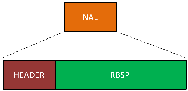
The header contains information about the type of data contained in the payload, and it can divided in three parts.
The header 0x67 ( which is the header in your NAL unit ) for example corresponds to the binary sequence 0110 0111. The first bit of this sequence ( which is a 0 ) is the forbidden zero and is used to verify if errors where encountered during the transmission of the packet.
The following 2 bits ( the 11 ) are called nal_ref_idc and they indicates if NAL unit is a reference field, frame or picture.
The remaining 5 bits specify the nal_unit_type. It specifies the type of RBSP data structure contained in the NAL unit. For a more detailed explanation of the NAL unit header you can refer to table 7.1 found in here or to the official RFC
Table 7-1 – NAL unit type codes, syntax element categories, and NAL unit type classes
| nal_unit_type | Content of NAL unit & RBSP syntax structure |
C | NAL unit type class [Annex A] |
NAL unit type class [Annex G & H] |
NAL unittype class [Annex I] |
| 0 | Unspecified | non-VCL | non-VCL | non-VCL | |
| 1 | Coded slice of a non-IDR picture slice_layer_without_partitioning_rbsp( ) |
2, 3, 4 | VCL | VCL | VCL |
| 2 | Coded slice data partition A slice_data_partition_a_layer_rbsp( ) |
2 | VCL | not applicable | not applicable |
| 3 | Coded slice data partition B slice_data_partition_b_layer_rbsp( ) |
3 | VCL | not applicable | not applicable |
| 4 | Coded slice data partition C slice_data_partition_c_layer_rbsp( ) |
4 | VCL | not applicable | not applicable |
| 5 | Coded slice of an IDR picture slice_layer_without_partitioning_rbsp( ) |
2, 3 | VCL | VCL | VCL |
| 6 | Supplemental enhancement information (SEI) sei_rbsp( ) |
5 | non-VCL | non-VCL | non-VCL |
| 7 | Sequence parameter set seq_parameter_set_rbsp( ) |
0 | non-VCL | non-VCL | non-VCL |
| 8 | Picture parameter set pic_parameter_set_rbsp( ) |
1 | non-VCL | non-VCL | non-VCL |
| 9 | Access unit delimiter access_unit_delimiter_rbsp( ) |
6 | non-VCL | non-VCL | non-VCL |
| 10 | End of sequence end_of_seq_rbsp( ) |
7 | non-VCL | non-VCL | non-VCL |
| 11 | End of stream end_of_stream_rbsp( ) |
8 | non-VCL | non-VCL | non-VCL |
| 12 | Filler data filler_data_rbsp( ) |
9 | non-VCL | non-VCL | non-VCL |
| 13 | Sequence parameter set extension seq_parameter_set_extension_rbsp( ) |
10 | non-VCL | non-VCL | non-VCL |
| 14 | Prefix NAL unit prefix_nal_unit_rbsp( ) |
2 | non-VCL | suffix dependent | suffix dependent |
| 15 | Subset sequence parameter set subset_seq_parameter_set_rbsp( ) |
0 | non-VCL | non-VCL | non-VCL |
| 16 – 18 | Reserved | non-VCL | non-VCL | non-VCL | |
| 19 | Coded slice of an auxiliary coded picture without partitioning slice_layer_without_partitioning_rbsp( ) |
2, 3, 4 | non-VCL | non-VCL | non-VCL |
| 20 | Coded slice extension slice_layer_extension_rbsp( ) |
2, 3, 4 | non-VCL | VCL | VCL |
| 21 | Coded slice extension for depth view components slice_layer_extension_rbsp( ) (specified in Annex I) |
2, 3, 4 | non-VCL | non-VCL | VCL |
| 22 – 23 | Reserved | non-VCL | non-VCL | VCL | |
| 24 – 31 | Unspecified | non-VCL | non-VCL | non-VCL |
H.264 frame, slice, bitstream
A frame is a complete image, A frame used as a reference for predicting other frames is called a reference frame.
Frames encoded without information from other frames are called I-frames. Frames that use prediction from a single preceding reference frame (or a single frame for prediction of each region) are called P-frames. B-frames use prediction from a (possibly weighted) average of two reference frames, one preceding and one succeeding.
https://en.wikipedia.org/wiki/Video_compression_picture_types
In the H.264/MPEG-4 AVC standard, the granularity of prediction types is brought down to the “slice level.” A slice is a spatially distinct region of a frame that is encoded separately from any other region in the same frame. I-slices, P-slices, and B-slices take the place of I, P, and B frames.
Now let’s look closer to our bitstream:
 |
| Figure 4. Detailed H.264 stream |
Any coded image contains slices, which in turn are divided into macroblocks. Most often, one encoded image corresponds to one slice. Also, one image can have multiple slices. The slices are divided into the following types:
Table 2. Slice types
| Type | Description |
|---|---|
| 0 | P-slice. Consists of P-macroblocks (each macro block is predicted using one reference frame) and / or I-macroblocks. |
| 1 | B-slice. Consists of B-macroblocks (each macroblock is predicted using one or two reference frames) and / or I-macroblocks. |
| 2 | I-slice. Contains only I-macroblocks. Each macroblock is predicted from previously coded blocks of the same slice. |
| 3 | SP-slice. Consists of P and / or I-macroblocks and lets you switch between encoded streams. |
| 4 | SI-slice. It consists of a special type of SI-macroblocks and lets you switch between encoded streams. |
| 5 | P-slice. |
| 6 | B-slice. |
| 7 | I-slice. |
| 8 | SP-slice. |
| 9 | SI-slice. |
Looks like table 2 contains some redundant data, But that is not true: types 5 – 9 mean that all other slices of the current image will be the same type.
H.264 sample PCAP file screenshot

we can see it send H.264 SPS, PPS/ SEI/IDR-Slice etc.
- Sequence Parameter Set (SPS). This non-VCL NALU contains information required to configure the decoder such as profile, level, resolution, frame rate.
- Picture Parameter Set (PPS). Similar to the SPS, this non-VCL contains information on entropy coding mode, slice groups, motion prediction and deblocking filters.
- Instantaneous Decoder Refresh (IDR). This VCL NALU is a self contained image slice. That is, an IDR can be decoded and displayed without referencing any other NALU save SPS and PPS.
- Access Unit Delimiter (AUD). An AUD is an optional NALU that can be use to delimit frames in an elementary stream. It is not required (unless otherwise stated by the container/protocol, like TS), and is often not included in order to save space, but it can be useful to finds the start of a frame without having to fully parse each NALU.
References
https://tools.ietf.org/html/rfc6184
http://gentlelogic.blogspot.com/2011/11/exploring-h264-part-2-h264-bitstream.html
http://gentlelogic.blogspot.com/2011/11/exploring-h264-part-1-color-models.html
https://yumichan.net/video-processing/video-compression/introduction-to-h264-nal-unit/